THE NDIR SENSOR MANUFACTURING LINE
We make no mystery about it: Non-Dispersive Infrared (NDIR) technology is at the core of our DNA. This is completely designed and manufactured at the NET headquarters in Milan, Italy and our staff is constantly working to extend it, improve it and optimize it – and today, we offer the most extensive NDIR range on the market.
Let’s take a closer look at how our NDIR sensors are made every day!
STEP 1 – SENSOR ASSEMBLY
Through a network of proven and longstanding partners, all located in close proximity of NET, critical parts such as metal sensor housings and sensor PCBs are continuously procured. Shortly after receiving the necessary incoming controls, the parts are sent to the sensor assembly line.
PCB may need to be completed with dedicated optical parts such as special NDIR sources or pyroelectric detectors before the assembly.


")
Mechanical components normally consist of the sensor external housings, the internal optical path part (which vary with the specific sensor model), mesh and PTFE filters to protect the optical parts from external agents.
The parts are mounted together to form the base sensor assembly ready for the following phases.
An important procedural step during this phase is tracking via bar code the production lot of each single component forming an assembly. This ensure complete traceability of each future sensor, and in case of malfunctioning we can go back and determine which components were used in assembling it.
STEP 2 – SENSOR CONFIGURATION
A single specific hardware assembly may be used to create several different sensor part numbers, differing for target gas, measuring range and functioning parameters – impacting output, response time, sensor behavior, self-calibration routines and other variables.
For this reason, immediately after the assembly phase is completed, each unit is “christened” within our system, assigned a unique serial number and configured with the specific set of functioning parameters defined by the specific part number.
This is performed on a dedicated facility able to simultaneously perform the configuration described above on up to 144 sensors. Data and settings for each specific sensor are saved in our production data base for future reference.


STEP 3 – SENSOR BURN-IN
The burn in consists in exercising the sensor for a specified length of time by powering it on under supervised conditions. The aim of this process at NET is to allow a complete stabilization of the electronic components, especially the sensor infrared source, and the electronic signals before the complete assembly enters the calibration phase.
Without a prior burn in, the sensor components may otherwise stabilize during the calibration determining a different behavior between the earlier and the final stages and therefore compromising the reliability and consistency of the calibration.
We have described this phase in detail in a dedicated article.
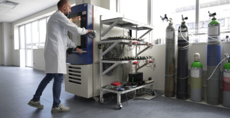
STEP 4 – SENSOR CALIBRATION
To ensure maximum accuracy and dependability, each NET NDIR sensor is individually calibrated. An automatic system designed and built in-house allow us to complete long and complexes cycles for up to 144 sensors per batch, while ensuring consistency of results and storage of an ever-increasing data base of information.
Each type of sensor in our range follows an individual cycle – a specific sequence of gas concentration steps across the desired measuring range, repeated over a number of environmental conditions within a climatic chamber. At each step, signal data from each individual sensor is stored by the system and matched with the record corresponding to the sensor serial number. At the end of the process, the optimal linearization curve of each sensor is determined, guaranteeing the best performances across the measuring and environmental ranges.
The system is further described in a dedicated article.

STEP 5 – SENSOR POTTING
To ensure optimal protection from external agents, contamination and humidity, after calibration each sensor bottom is filled with a selected type of epoxy (different for certified and non-certified products). This insulates the sensor electronic boards from the environment and the only way in for the target gas and other agents is through the top filter and the optical path.
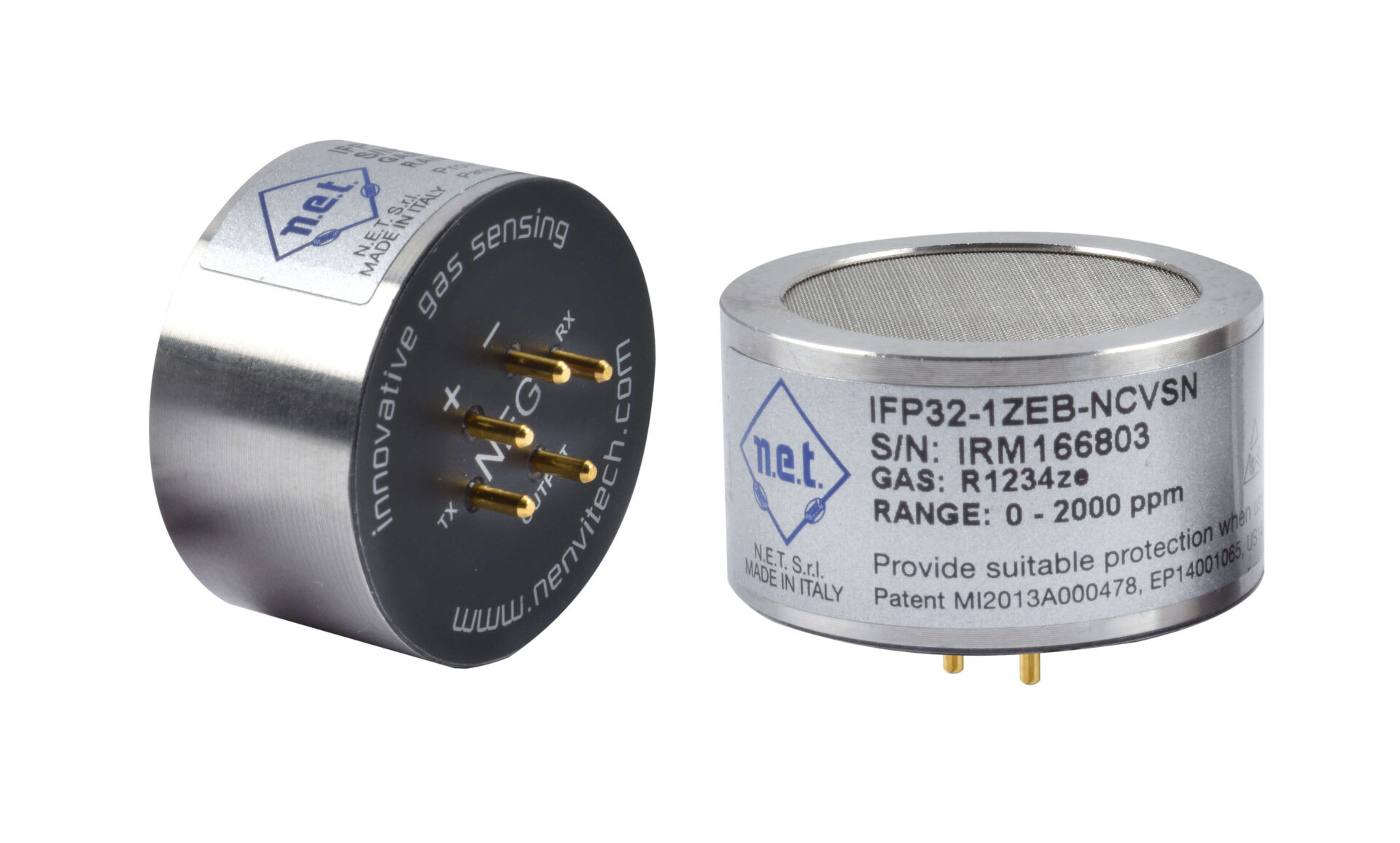
After the epoxy has dried, we apply a sticker on the bottom of the sensor identifying each sensor pin and, as a finishing touch, we apply a product label listing the sensor part number, serial number, target gas, measuring range and other relevant information, including Ex marking for certified sensors.

STEP 6 – INDIVIDUAL TESTS
This phase is optional in most cases and dedicated to sensors which were deemed by experience in need of a final control after calibration, especially for sensors going through extreme temperatures during the calibration cycle. The selected sensors are individually tested against selected gas concentrations to verify full compliance with their stated specifications. The test conditions are designed to verify the sensor calibration effectiveness in conditions which have a track record of being critical. Sensors which do not pass the individual test may have to go through a new calibration cycle (and go back to step 4).
Now take a live look inside our new headquarters and explore our manufacturing facilities!